The Latest At Valley Forge
Fastener Crosstalk is the phenomenon where as fasteners are tensioned, they affect the load on other fasteners around them, essentially speaking to each other.
We have been wanting to make a video that can show this intriguing display for a very long time. Because the Maxbolt™ can measure continuous tension in the fastener, there is simply nothing that can show crosstalk in fasteners better.
In making this video, an actual installation was done on an ASME class 300 flange unit. All measurements were recorded precisely during tightening with 3/4″ Maxbolt fasteners and a spiral wound gasket installed. The full procedure was: (1-5-3-7), (2-6-4-8) PCC- Legacy Modified.
First Pass: Fasteners were torqued to 55 ft lbs, which targeted 22% on the Maxbolt (40% of target torque STAR)
Second Pass: Fasteners were torqued to 138 ft lbs, which targeted 50% on the Maxbolt (100% of target torque STAR)
Third and Final Pass: Fasteners were torqued to 138 ft lbs, which targeted 50% on the Maxbolt (100% of target torque CW)
Calculated with K= 0.17, 100% on MB = 26,700 Lbf
During the first pass, there was a considerable amount of crosstalk in the bolts. A the very beginning all fasteners started hand tightened, but we found many were much more loose than this as we tried to torque them. During the second and final pass though, we really see the bolts crosstalking to each other and it reflected in their tension in the video. This video animation of an actual installation illustrates that controlling a joint with torque results in uneven tensioning of the fastener because of fastener crosstalk. With Maxbolts, designed preloads can be monitored continuously and show +/- 5% of targeted load to ASTM F2482 standards.
We hope you enjoy this video as much as we enjoyed making it. Please share and stay tuned for more animations like these to see more of the Fastener Revolution.
As Published In The January 2016 Issue of Wind Systems |
Valley Forge & Bolt Mfg. Co. uses innovative bolting technology to revolutionize bolted joints with its new wireless load-monitoring capabilities. Starting from its patented load-indicating technology, Valley Forge is now taking it a step further in allowing the user to monitor the load on a critically bolted joint from a remote location.
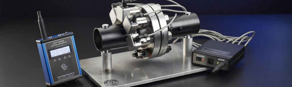
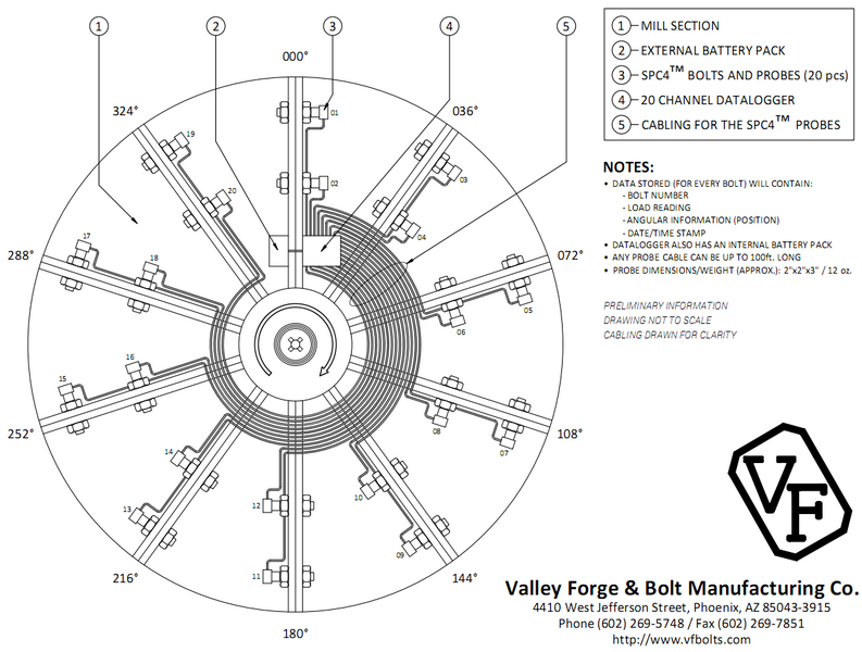
The company’s well-known load-indicating technology started with the Maxbolt™ load-indicating fastener that continuously measures and displays the amount of tension in a bolt or stud. The fastener offers a simple method for accurate joint assembly and is the only product available for most applications that will continually monitor clamping force while the fastener is in service. Then the company introduced the SPC4™ load-indicating system, which allows the user to constantly monitor the clamp load of any SPC4 bolted joint by easily attaching a probe to the datum disc located on the end of the fastener. The user is able to read the value on a handheld battery-powered digital monitor with optional data gathering and storage of the bolted joint available.
Valley Forge’s newest technology has taken the patented SPC4 technology and made remote reading a reality. With the new wireless load-monitoring device, SPC4 fasteners are assembled with a small probe attached to the datum disc. This probe then remains with the fastener assembly while in service. The probe allows the load of the fastener to be relayed to a receiving station that can be located anywhere the user chooses. The receiving station displays the load as a percentage of the fastener’s total capacity, as designed for the specific application.
The Wireless SPC4 load monitor is now in the beta testing stages and is being applied on a large rotating piece of machinery. One system consists of four probes or channels with a wireless remote reader for fixed applications. No positional information is included in this system, but it has a long range of up to 2,000 feet in ideal conditions. It can be designed to use another wireless technology, but generally, the longer the range is, the shorter the battery life will be. Another system monitors and logs 20 probes or channels for rotating applications that can be attached to an optional wireless transmitter. The system can be equipped with an optional programmable 5-megapixel video camera to send alerts in unattended installations or automate some tasks. The range would be shorter than the previous system.
The configuration of this technology can be tailored to specific customer needs, including the number of channels, frequency of reading, battery life, auxiliary outputs, and data logging. Other capabilities include sensors relaying positional information of each fastener and real-time clock circuit, if time records are desired.